
A heat engine is a device used to extract heat from a source and then convert it into mechanical work that is used for all sorts of applications. For example, a steam engine on an old-style train can produce the work needed for driving the train. Several questions emerge from the construction and application of heat engines. For example, what is the maximum percentage of the heat extracted that can be used to do work? This turns out to be a question that can only be answered through the second law of thermodynamics.
The second law of thermodynamics can be formally stated in several ways. One statement presented so far is about the direction of spontaneous heat flow, known as the Clausius statement. A couple of other statements are based on heat engines. Whenever we consider heat engines and associated devices such as refrigerators and heat pumps, we do not use the normal sign convention for heat and work. For convenience, we assume that the symbols \(Q_h, \, Q_c\), and W represent only the amounts of heat transferred and work delivered, regardless what the givers or receivers are. Whether heat is entering or leaving a system and work is done to or by a system are indicated by proper signs in front of the symbols and by the directions of arrows in diagrams.
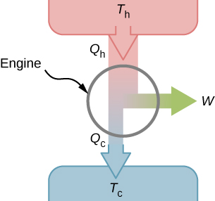
It turns out that we need more than one heat source/sink to construct a heat engine. We will come back to this point later in the chapter, when we compare different statements of the second law of thermodynamics. For the moment, we assume that a heat engine is constructed between a heat source (high-temperature reservoir or hot reservoir) and a heat sink (low-temperature reservoir or cold reservoir), represented schematically in Figure \(\PageIndex\). The engine absorbs heat \(Q_h\) from a heat source ( hot reservoir ) of Kelvin temperature \(T_h\), uses some of that energy to produce useful work W, and then discards the remaining energy as heat \(Q_c\), into a heat sink ( cold reservoir ) of Kelvin temperature \(T_c\). Power plants and internal combustion engines are examples of heat engines. Power plants use steam produced at high temperature to drive electric generators, while exhausting heat to the atmosphere or a nearby body of water in the role of the heat sink. In an internal combustion engine , a hot gas-air mixture is used to push a piston, and heat is exhausted to the nearby atmosphere in a similar manner.
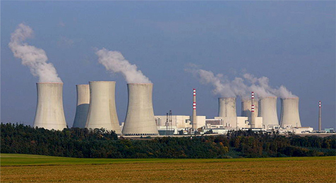
Actual heat engines have many different designs. Examples include internal combustion engines, such as those used in most cars today, and external combustion engines, such as the steam engines used in old steam-engine trains. Figure \(\PageIndex\) shows a photo of a nuclear power plant in operation. The atmosphere around the reactors acts as the cold reservoir, and the heat generated from the nuclear reaction provides the heat from the hot reservoir.
Heat engines operate by carrying a working substance through a cycle. In a steam power plant, the working substance is water, which starts as a liquid, becomes vaporized, is then used to drive a turbine, and is finally condensed back into the liquid state. As is the case for all working substances in cyclic processes, once the water returns to its initial state, it repeats the same sequence.
For now, we assume that the cycles of heat engines are reversible, so there is no energy loss to friction or other irreversible effects. Suppose that the engine of Figure \(\PageIndex\) goes through one complete cycle and that \(Q_h\), \(Q_c\), and W represent the heats exchanged and the work done for that cycle. Since the initial and final states of the system are the same, \(\Delta E_ = 0\) for the cycle. We therefore have from the first law of thermodynamics,
\[\begin W &= Q - \Delta E_ \\[4pt] &= (Q_h - Q_c) - 0, \label \end \]
\[W = Q_h - Q_c.\label \]
The most important measure of a heat engine is its efficiency (e) , which is simply “what we get out” divided by “what we put in” during each cycle, as defined by
With a heat engine working between two heat reservoirs, we get out \(W\) and put in \(Q_h\), so the efficiency of the engine is
Here, we used Equation \ref, in the final step of this expression for the efficiency.
A lawn mower is rated to have an efficiency of \(25\%\) and an average power of 3.00 kW. What are
Strategy
From the average power—that is, the rate of work production—we can figure out the work done in the given elapsed time. Then, from the efficiency given, we can figure out the minimum heat discharge \(Q_c = Q_h(1 - e)\) with \(Q_h = Q_c + W\).
Solution
Significance
As the efficiency rises, the minimum heat discharged falls. This helps our environment and atmosphere by not having as much waste heat expelled.
This page titled 4.3: Heat Engines is shared under a CC BY 4.0 license and was authored, remixed, and/or curated by OpenStax via source content that was edited to the style and standards of the LibreTexts platform.